
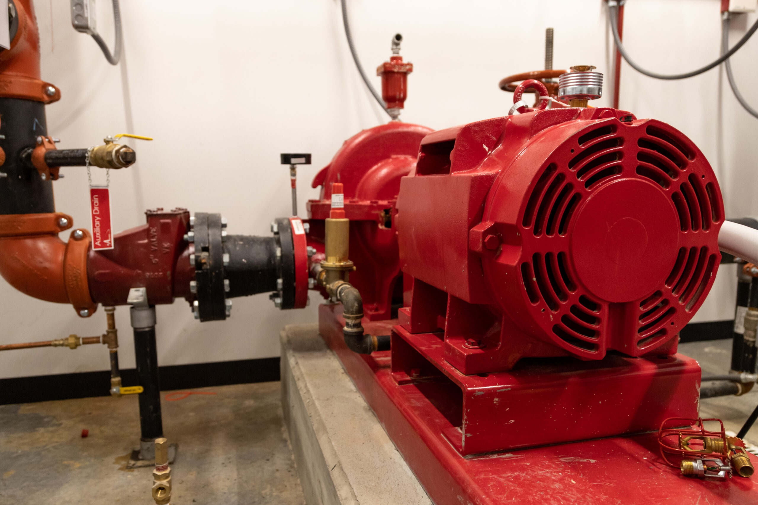
A fire pump is designed to deliver the required water flow and pressure during a fire emergency. However, its performance depends on more than the pump's rated capacity, motor size, or discharge pressure. The piping arrangement that supplies water to the pump also plays a critical role.
Fire pump suction piping directly influences how efficiently water enters the pump. An improperly designed suction arrangement can create excessive friction losses, uneven water flow, turbulence, and pressure fluctuations. These conditions may reduce pump performance and increase the risk of cavitation.
Even a correctly selected fire pump may fail to deliver its expected performance if the suction side of the system restricts water supply. This makes suction pipe configuration an important consideration during fire protection system design, equipment selection, and installation.
Understanding pipe sizing, alignment, fittings, reducers, water supply conditions, and applicable installation standards helps engineers develop reliable fire pump installations that can perform when needed.
1. Why Is Suction Pipe Configuration Important for Fire Pumps?
The suction side of a fire pump carries water from a storage tank, municipal supply, reservoir, or another approved water source into the pump inlet.
Its primary responsibility is to provide an adequate and consistent water supply under the operating conditions required by the fire protection system.
The configuration of this piping affects several important performance factors:
Water flow: Pipe diameter and layout influence how much water can reach the pump.
Suction pressure: Excessive friction losses can reduce the pressure available at the pump inlet.
Flow stability: Poorly arranged fittings can create turbulence and uneven water distribution.
Cavitation risk: Insufficient suction pressure can contribute to vapor formation inside the pump.
Pump efficiency: Unnecessary hydraulic losses can affect the pump's ability to achieve its required operating conditions.
A well-designed suction arrangement helps the pump receive water without unnecessary restrictions. This is particularly important in high-rise buildings, industrial facilities, warehouses, hospitals, and other properties where fire protection systems require dependable water delivery.
2. How Does Suction Pipe Diameter Affect Pump Performance?
Pipe diameter is one of the most important factors in fire pump suction design. If the suction pipe is too small, water must travel at a higher velocity to deliver the required flow.
Higher velocity generally increases friction losses, which can reduce the pressure available at the pump inlet.
For example, consider a fire pump designed to deliver 1,000 gallons per minute (GPM). If the suction pipe is undersized, the increased water velocity can create additional resistance before water reaches the pump.
This can result in:
Increased friction losses.
Reduced available suction pressure.
Greater sensitivity to water supply fluctuations.
Increased risk of cavitation under unfavorable operating conditions.
An appropriately sized suction pipe helps maintain acceptable water velocity and minimizes unnecessary hydraulic resistance.
However, selecting a pipe diameter should not rely on a general rule of thumb alone. Engineers must consider the pump's rated flow, available water supply, pipe material, equivalent fitting lengths, actual layout, and applicable NFPA 20 requirements.
3. Why Should Straight Pipe Be Provided Before the Pump Inlet?
Water does not always enter a pump in a uniform flow pattern. Elbows, tees, valves, and other fittings can change the direction and distribution of water moving through the suction line.
When these fittings are installed too close to the pump inlet, they may create turbulence and uneven flow across the impeller eye.
This can negatively affect pump operation, particularly at higher flow rates.
Providing an appropriate straight length of pipe before the pump inlet helps reduce disturbances and allows water to approach the pump more uniformly.
The required arrangement depends on the pump type, inlet geometry, fitting configuration, and applicable installation requirements.
Engineers should pay particular attention to:
Elbows positioned close to the suction flange.
Multiple directional changes within a short distance.
Tees that create uneven flow distribution.
Fittings that introduce swirling or asymmetric flow.
A straight suction approach is not simply a matter of appearance. It supports more predictable hydraulic conditions at the pump inlet.
4. How Do Elbows and Tees Influence Suction Flow?
Elbows and tees are often necessary to connect the water source, suction header, and fire pump. However, their placement can significantly influence hydraulic conditions.
Every change in flow direction introduces some resistance. Closely spaced elbows, sharp directional changes, and poorly positioned tees can increase turbulence and pressure losses.
The issue becomes particularly important when a fitting is installed immediately upstream of a pump suction flange.
For horizontal split-case fire pumps, NFPA 20 includes specific requirements concerning the orientation and positioning of elbows and tees near the suction inlet. The arrangement depends on the fitting's plane relative to the pump shaft.
Engineers should therefore evaluate:
The number of elbows and tees in the suction arrangement.
The distance between fittings and the pump inlet.
The orientation of fittings relative to the pump shaft.
The additional friction losses created by the piping layout.
Whether the arrangement provides sufficiently uniform water flow.
Avoiding unnecessary fittings can simplify the suction arrangement and reduce hydraulic losses. However, compliance must be evaluated against the requirements applicable to the particular pump configuration.
5. Why Are Eccentric Reducers Used in Fire Pump Suction Piping?
A fire pump's suction pipe and inlet flange do not always have the same diameter. When their sizes differ, an appropriate reducer is needed to connect them.
An eccentric reducer is commonly used because its offset design helps prevent air pockets from forming in the suction line.
Air accumulation is a concern because it can interrupt uniform water flow, affect pump operation, and contribute to vibration and performance problems.
The installation orientation is equally important.
Under the 2025 edition of NFPA 20, Section 4.16.6.4 addresses eccentric tapered reducers or increasers and requires their installation to avoid air pockets. The standard also distinguishes the installation orientation based on whether the supply approaches from above.
Consider these general arrangements:
Horizontal suction piping: The reducer is generally installed with its flat side on top.
Supply entering from above: The flat side is installed on the bottom to avoid air accumulation.
Using an incorrectly oriented reducer can defeat its purpose and introduce an unwanted air pocket into the suction arrangement.
Engineers should verify the reducer's orientation against the actual piping geometry and the applicable NFPA requirements rather than relying on a standard installation sketch for every situation.
6. How Can Poor Suction Configuration Cause Cavitation?
Cavitation is one of the most damaging problems associated with inadequate pump suction conditions.
It occurs when the local liquid pressure inside the pump falls below the liquid's vapor pressure, allowing vapor bubbles to form. As these bubbles move into higher-pressure regions, they collapse.
Repeated bubble formation and collapse can damage impeller surfaces and other internal pump components.
Poorly configured suction piping can contribute to this condition through:
Excessive friction losses.
Undersized suction pipes.
Restricted valves or partially obstructed passages.
Unnecessary elbows and fittings.
Insufficient available water supply.
Excessive water temperature.
Poor inlet flow distribution.
Cavitation may produce unusual noise, vibration, fluctuating pressure, and reduced hydraulic performance.
However, these symptoms are not exclusive to cavitation. A proper investigation should include suction pressure measurements, water supply conditions, operating flow, and pump performance data.
A useful engineering consideration is Net Positive Suction Head (NPSH). Available NPSH (NPSHa) describes the suction energy available at the pump, while required NPSH (NPSHr) represents the minimum level established by the pump manufacturer under specified operating conditions.
The available NPSH should provide an appropriate margin over the required NPSH.
For fire protection applications, engineers must also verify the specific suction pressure requirements established by NFPA 20. A favorable NPSH calculation alone does not establish compliance with the fire pump installation standard.
7. Why Does Suction Pipe Alignment and Support Matter?
Suction piping must be properly aligned with the pump inlet. Poor alignment can introduce mechanical stress into the pump casing and connected components.
When piping is forced into position during installation, the resulting strain can affect flange connections, seals, bearings, and overall equipment reliability.
Independent pipe support is important because the pump should not carry the weight of the connected suction pipeline.
Proper installation should account for:
Pipe weight and water-filled operating weight.
Structural movement and vibration.
Flange alignment.
Thermal expansion where applicable.
Independent support near the pump.
Strain relief where required by the installation arrangement.
NFPA 20 addresses strain relief where a pump and its suction supply are located on separate foundations with rigid interconnecting piping.
Correct alignment and support help protect the pump from unnecessary mechanical loads and reduce the possibility of leakage or connection failure.
8. How Does Water Source Configuration Affect Pump Suction?
The water source is just as important as the piping arrangement connecting it to the pump.
Fire pumps may receive water from municipal supplies, dedicated storage tanks, reservoirs, or other approved sources. Each arrangement creates different hydraulic conditions.
Municipal water supply
When a fire pump draws from a municipal supply, engineers must evaluate available pressure, flow capacity, supply fluctuations, and the pressure remaining at the pump suction flange under demanding operating conditions.
Fire water storage tanks
Tank-fed systems require careful consideration of tank elevation, minimum operating water level, outlet location, and suction pipe arrangement.
An improperly positioned tank outlet can create unfavorable inlet conditions. Vortex formation may also introduce air into the suction line, affecting pump operation.
Reservoirs and open water sources
These arrangements require attention to intake geometry, water levels, screening, and the possibility of debris entering the suction system.
For tank installations, NFPA 20 addresses anti-vortex arrangements, referring to NFPA 22 for applicable requirements.
The goal is to ensure that the pump receives an adequate water supply throughout the required operating period, including when the source reaches its lowest permitted operating level.
9. What Does NFPA 20 Say About Fire Pump Suction Piping?
NFPA 20, Standard for the Installation of Stationary Pumps for Fire Protection, provides important requirements for fire pump suction arrangements.
The 2025 edition includes provisions covering suction pipe sizing, installation, valves, fittings, pressure conditions, and other components.
Some important design considerations include:
Design consideration | Engineering requirement |
|---|---|
Suction pressure | Evaluate pressure at the pump suction flange under maximum-flow conditions |
Pipe sizing | Follow the applicable suction pipe sizing requirements |
Pipe installation | Avoid air leaks and air pockets |
Suction valves | Use the required listed indicating valve |
Reducers | Use eccentric tapered reducers or increasers where applicable |
Multiple pumps | Arrange the common suction supply to provide the required proportional supply to each pump |
Tank outlets | Provide the required anti-vortex arrangement |
One particularly important requirement concerns suction pressure. Under Section 4.16.3.1 of the 2025 edition, the suction piping must be sized so that, with the applicable pumps operating at maximum flow, the gauge pressure at the suction flanges is 0 psi or higher. The standard also includes a specific provision for qualifying suction tank arrangements.
Engineers should consult the complete applicable edition, local codes, the authority having jurisdiction (AHJ), and equipment listing requirements before finalizing a design. Requirements can differ depending on the pump type and water supply arrangement.
10. What Are the Most Common Fire Pump Suction Piping Design Mistakes?
Even small installation errors can affect the hydraulic performance of a fire pump. Some problems are visible during installation, while others become apparent only when the system operates under demanding conditions.
Here are common mistakes engineers and contractors should watch for:
1. Using undersized suction pipes
Smaller pipes can increase water velocity and friction losses, making it harder for the pump to receive the required water supply.
2. Installing fittings too close to the pump
Poorly positioned elbows and tees can disturb water flow and create unfavorable inlet conditions.
3. Incorrect reducer orientation
A poorly installed eccentric reducer can create air pockets instead of preventing them.
4. Allowing air to enter the suction line
Air leaks and trapped air can interfere with pump operation and reduce hydraulic stability.
5. Adding unnecessary restrictions
Unapproved or unsuitable devices in the suction line can restrict water flow. NFPA 20 specifically limits the devices permitted in fire pump suction piping.
6. Ignoring pipe alignment
Misaligned connections and inadequate pipe supports can introduce mechanical stress into the pump assembly.
7. Overlooking water source limitations
A correctly sized pipe cannot compensate for an inadequate water supply. Available pressure, flow capacity, and minimum water levels must all be considered.
Addressing these issues during the design and installation stages helps reduce the possibility of performance problems during fire pump operation.
11. How Should Engineers Evaluate Fire Pump Suction Piping Performance?
A well-designed suction arrangement should be evaluated through hydraulic calculations, installation inspections, and pump performance testing.
Engineers should not assume that a system will perform correctly simply because its pipe dimensions appear suitable on paper.
A practical evaluation should include the following steps:
Step 1: Verify the water supply
Determine the available water pressure, flow capacity, and minimum operating water level. Confirm that the source can support the required fire protection demand.
Step 2: Review pipe sizing
Check the suction pipe diameter against the required flow rate and applicable NFPA 20 provisions.
Step 3: Calculate friction losses
Account for straight pipe lengths, elbows, tees, valves, reducers, and other relevant components.
Step 4: Inspect the inlet arrangement
Check reducer orientation, fitting placement, pipe alignment, and the possibility of air accumulation.
Step 5: Verify mechanical support
Ensure that the suction piping is independently supported and does not impose excessive loads on the pump.
Step 6: Conduct acceptance testing
Verify the installed fire pump's performance through the applicable acceptance testing procedures. Compare measured flow, suction pressure, and discharge pressure against the approved design requirements and manufacturer's performance data.
Testing at churn, rated flow, and 150% of rated flow is an important part of the standard fire pump performance evaluation, subject to the applicable testing requirements.
The results help identify hydraulic restrictions, unexpected pressure losses, and other installation-related issues that may not be apparent during a visual inspection.
12. Why Is Proper Suction Design Becoming More Important in Modern Fire Protection Systems?
Modern commercial and industrial buildings increasingly require fire protection systems capable of handling demanding water supply conditions.
High-rise developments, large warehouses, manufacturing facilities, healthcare buildings, and mixed-use properties can have complex hydraulic requirements.
As a result, fire pump design is becoming more focused on accurate hydraulic calculations, equipment compatibility, installation quality, and measurable performance.
Several engineering considerations are particularly relevant:
Hydraulic modeling: More detailed calculations help engineers evaluate pressure losses and water flow throughout complex piping arrangements.
Equipment compatibility: Suction pipe dimensions and configurations must match the selected pump's hydraulic and mechanical requirements.
Performance verification: Acceptance testing provides measurable evidence of actual pump performance.
Water supply reliability: Engineers must account for variations in municipal pressure and available storage capacity.
Code compliance: Applying the correct NFPA 20 edition and local requirements helps prevent design and installation errors.
These considerations reinforce an important principle: fire pump performance depends on the entire hydraulic arrangement, not just the pump itself.
Frequently Asked Questions
1. What is the purpose of fire pump suction piping?
Fire pump suction piping carries water from an approved water source to the pump inlet. Its purpose is to provide sufficient water flow and maintain suitable suction pressure during pump operation.
2. What happens if fire pump suction piping is undersized?
Undersized suction piping can increase water velocity and friction losses. This may reduce available suction pressure, increase cavitation risk, and prevent the pump from achieving its intended operating conditions.
3. Why are eccentric reducers used in fire pump suction lines?
Eccentric reducers help connect pipes of different diameters while minimizing the possibility of air pockets. Their orientation depends on the suction piping arrangement and applicable NFPA 20 requirements.
4. Can an elbow be installed directly before a fire pump?
Elbow placement depends on the pump configuration and the applicable installation requirements. For horizontal split-case pumps, NFPA 20 specifies restrictions based on the elbow's orientation relative to the pump shaft. Engineers should verify the exact arrangement before installation.
5. How does suction pressure affect fire pump performance?
Suction pressure determines the pressure available at the pump inlet. If it becomes too low, the pump may experience reduced performance and an increased risk of cavitation.
6. What is the recommended suction pipe velocity for a fire pump?
There is no single velocity value that should be applied universally to every fire pump installation. Pipe sizing must follow applicable NFPA 20 requirements and account for rated flow, available supply pressure, friction losses, and the specific system configuration.
7. What is the difference between suction lift and positive suction pressure?
Positive suction pressure means water enters the pump under pressure, while suction lift occurs when the pump must draw water from a source below its centerline. Standard fire pump installations generally require positive-pressure suction arrangements, subject to specific permitted configurations and applicable requirements.
8. How can engineers identify suction piping problems?
Common warning signs include fluctuating suction pressure, unusual pump noise, vibration, reduced discharge pressure, and inconsistent flow. Hydraulic measurements and pump performance testing help determine the underlying cause.
9. Does NFPA 20 specify suction pipe sizing requirements?
Yes. NFPA 20 includes requirements for suction pipe sizing, pressure conditions, valves, fittings, and installation arrangements. The applicable requirements depend on the pump type and water supply configuration.
10. Why is independent pipe support necessary?
Independent support prevents the weight and movement of suction piping from placing unnecessary mechanical stress on the pump casing and its connections.
Conclusion
Fire pump performance begins before water reaches the impeller. The suction piping arrangement determines how effectively water enters the pump and whether the equipment can operate under the hydraulic conditions required by the fire protection system.
Pipe diameter, fitting placement, reducer orientation, suction pressure, water source conditions, and proper mechanical support all contribute to reliable operation.
For engineers, contractors, and building project teams, evaluating these factors during the design and equipment selection stages can help prevent avoidable hydraulic and installation problems.
A properly designed fire pump suction piping arrangement is an essential part of a dependable fire protection system. Selecting the right pump is important, but ensuring that it receives an adequate and unrestricted water supply is equally critical.