
The monoblock stopper rod is a critical flow-control component in the continuous casting process. Installed in the ladle or tundish slide-gate system, the stopper rod regulates molten steel flow by adjusting the opening area between the nozzle seat and its controlled orifice. Because it is directly exposed to high-temperature steel, aggressive slag chemistry, thermal shock, and mechanical load, its performance significantly influences casting stability, steel cleanliness, and product quality.
Understanding the structural characteristics, materials, degradation mechanisms, and operational best practices of the monoblock stopper rod is essential for achieving long casting sequences and minimizing risk of nozzle leakage or flow instability. This article summarizes the key technical tips every steel plant should know.
1. Understand the Structure and Working Principle of the Monoblock Stopper Rod
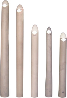
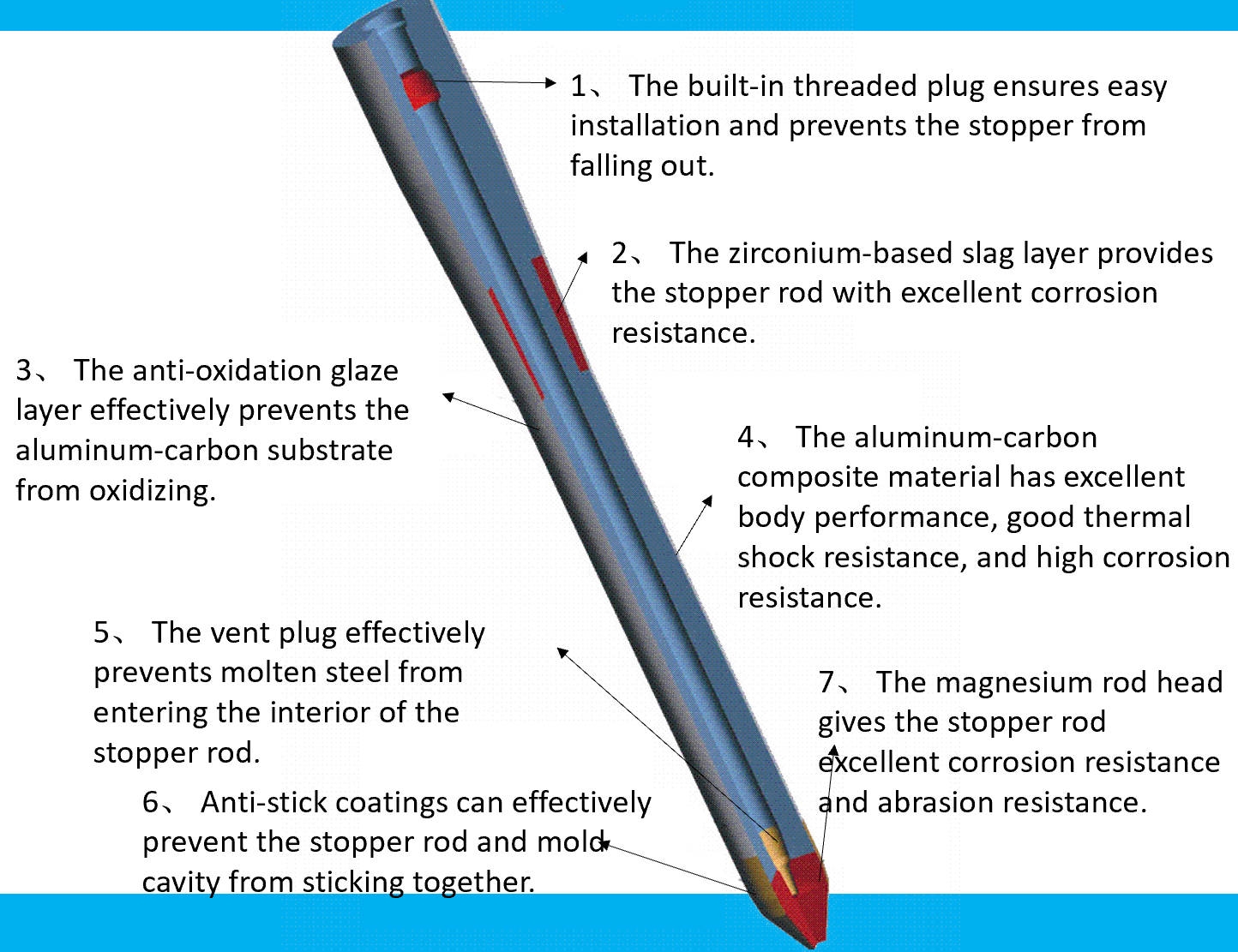
A monoblock stopper rod is a single-piece, integrated ceramic system designed to precisely control molten steel flow. It typically consists of:
Tip (Working end)
Exposed directly to molten steel
Requires high erosion resistance and thermal shock stability
Often
Body (Shaft)
Transfers mechanical force to the tip
Must be strong yet lightweight to reduce arm load
Usually alumina-graphite with high flexural strength
Up
With
Requires good dimensional tolerance and mechanical integrity
The key working principle is:
The stopper rod moves vertically to adjust the annular opening between the rod tip and nozzle seat.
This controls steel flow rate, jet length, and casting meniscus stability.
Smooth movement is essential to avoid flow surges and inclusion entrapment.
2. Choose the Proper Material System Based on Casting Requirements
Material
2.1 High-Zirconia Carbon (ZrO₂-C)
Excellent corrosion resistance against aggressive steels
Very stable against Al-killed steel environments
Preferred for long-sequence slab or bloom casting
2.2 To
Good thermal shock resistance
To
Economical and widely used
2.3 Low-Carbon or Carbon-Free Systems
Reduce carbon pick-up and CO bubble generation
Improve steel cleanliness for ultra-low-inclusion grades
Critical for interstitial-free and automotive steels
2.4 Tips for material selection
For stainless steel → use high-ZrO₂ systems
For high-aluminum steels → ensure anti-oxidation coatings
For long casting campaigns → use high-density, isopressed products
3. Pay Attention to Stopper Rod–Nozzle Seat Interaction
The interface between the stopper rod tip and nozzle seat is the most critical point in casting flow control.
Problems in this area can lead to:
Leakage
Turbulent flow
Uncontrolled casting speed
Accelerated clogging
Inclusion entrapment
Best practices:
Ensure precise geometry to achieve a uniform annular gap.
Avoid thermal mismatch between stopper rod and nozzle.
Use anti-oxidation, anti-slag-wetting coatings to reduce buildup.
Maintain alignment between stopper rod and nozzle bore.
A misalignment of even 1–2 mm can cause severe turbulence and steel quality defects.
4. Understand the Main Failure Mechanisms
A monoblock stopper rod faces multiple types of degradation. Knowing these mechanisms helps prevent premature failure.
4.1 Oxidation
Graphite in the refractory oxidizes when exposed to air or oxygen-rich slag.
→ leads to porosity growth, strength reduction, and erosion.
4.2 Slag Erosion
Basic slags (CaO-rich) or acidic slags (SiO₂-rich) dissolve refractory surfaces.
→ anti-slag coatings are essential.
4.3 Thermal Shock
The rod experiences rapid temperature change when first immersed.
→ high-modulus graphite and fine-structure alumina reduce spalling.
4.4 Mechanical Load & Wear
Vibration or actuator misalignment causes tip abrasion.
→ requires strong bonding and consistent density.
4.5 Steel–Refractory Reaction (especially in Al-killed steel)
Al₂O₃ deposition at the interface can cause:
Increased resistance to movement
Flow instability
Premature clogging
5. Control Operational Conditions to Extend Stopper Rod Life
Proper operation can increase stopper rod campaign life by 30–50%.
5.1 Preheating
Gentle, controlled preheating prevents thermal shock.
5.2 Correct Argon Injection (if applicable)
Too low → clogging increases
Too high → turbulence and re-entrainment
Optimal → improves steel cleanliness and flow stability
5.3 Smooth Actuator Motion
A jerking motion causes:
Flow surges → inclusions
Wear on the nozzle seat
Risk of breakthrough
Modern electro-servo stopper actuators provide better stability.
5.4 Accurate Stopper Position Calibration
Misalignment can:
Cause eccentric wear
Increase clogging
Lead to molten steel leakage
6. Optimize Stopper Rod Geometry for Your Casting Mode
Different casting processes require different stopper geometries.
6.1 Long strand slab casting
Use elongated tips for deeper penetration
Prefer high-ZrO₂ systems
6.2 Billet and bloom casting
Shorter tapered designs for fast response
Require high thermal shock resistance
6.3 High-speed casting lines
Aerodynamic designs to reduce flow separation
Optimized surface coatings
7. Maintenance and Inspection Tips
To ensure consistent casting performance:
Before casting:
Check for cracks, tip defects, surface spalling
Confirm actuator calibration
Verify coating uniformity
During casting:
Monitor stopper movement behavior
In
After casting:
Examine the rod and nozzle seat for:
Buy
Clogging deposits
Chemical attack zones
Documenting the damage provides guidance for future material optimization.
Conclusion
The monoblock stopper rod is a mission-critical flow-control component in continuous casting. Proper understanding of its materials, design principles, failure mechanisms, and operational considerations can significantly enhance casting stability and steel quality. By selecting high-performance materials, optimizing rod–nozzle interaction, controlling thermal and chemical environments, and maintaining precise operational control, steel plants can extend campaign life and achieve superior metallurgical results.More information,please visit HYRE
